-Mobility Services, network management, network unification, access points, and clients device are component included in the cisco unified wireless network
-Wireless network use CSMA/CA protocol to Avoid collision on the network
-IEEE 802.11 is the standard that defines wireless LANs
-A 20% overlap is recommend by adjacent wireless cells
-Service set identifier (SSID) is a name that identifies a particular 802.11 wireless LAN,
-The basic service set (BSS) is the basic building block of an 802.11 wireless LAN. In infrastructure mode, a single access point (AP) together with all associated stations (STAs) is called a BSS.
-An independent basic service set (IBSS) is ad-hoc network of client devices without a controlling access point. in which case the SSID is chosen by the client device that starts the network, and broadcasting of the SSID is performed in a pseudo-random order by all devices that are members of the network.
-An extended service set (ESS) is a set of one or more interconnected BSSs and integrated local area networks that appear as a single BSS to the logical link control layer at any station associated with one of those BSSs
Wednesday, August 24, 2011
Monday, June 20, 2011
Wireless
Just a Little
In the split MAC method, the three functions handled by the WLAN controller are,
802.11 association and re -association
802.11 frame translation and bridging
802.11 authentication
In the split MAC method, the three functions handled by the WLAN controller are,
802.11 association and re -association
802.11 frame translation and bridging
802.11 authentication
Tuesday, June 14, 2011
Private VLANs
Worked on Private VLANs today and they are petty cool. They allow you to segregate hosts without re-IPing them. First the switch must be in Transparent mode, (found this out the hard way)
 Then create the Secondary Vlans. There are 2 types, Community were the members can talk with each other, and Isolated were members can not talk to each other. In both case the members can talk to one other special port.
Vlan ID# 201
private-vlan type (Community)
Vlan ID# 202
private-vlan type (Isolated)
Than make the Primary vlan and associate it to the secondaries
Vlan ID# 2private-vlan primary
private-vlan association list (201,202)
There are 2 port types, Host which are connected to members of the secondary Vlans, and Promiscuous which is connected to the router and is no in any secondary Vlans but is in the primary VLAN.
To configute the access ports for member hosts and associte it to the primary and seconary vlans
int f0/1
sw mode private-vlan host
sw private-vlan host-association Primary Vlan Secondary Vlan (2 201)
To configure a port that connect to a router and associte it to the primary and seconary vlans
int f0/24
sw mode private-vlan promiscuous
sw privet-vlan mapping Primary Vlan Secondary Vlans (2 201,202)
We can use the "sh int status" command to see that f0/1 is in two vlans 2 and 201, and that int f0/24 is ???
Thursday, April 21, 2011
Etherchannal
Link Aggregation allows the grouping of up to 8 physical ports into one link.all port in the group must be the same, speed, dup, access (same vlan) or trunk (same encap, vlans allow).
Also uses a load balancing method
- PAgP, is cisco and has three port modes, auto and desirable, and on.
- If two link are in desirable they will not negotiate a link
- If connecting to servers which do not use PAgP then use silent
- LACP, is not cisco and has two modes, active and passive
- if two links are in Passive they will not negotiate a link
- ON, uses no negotiation.
- Must be set on all
- Switch(config)#interface port-channel 1
- Switch(config-if)#channel-group 1 mode on\des\auto\act\pass
- Switch(config-if)#channel-protocol pagp\lacp
- Switch(config)#int port-channel 1
- Switch(config-if)#int mode trunk
Also uses a load balancing method
ACLs on a switch
We are talking about filtering traffic going through the switch, not just using ACL on the switch's vty lines. The switch can use Router ACLs (RACL), Vlan ACLs (VACL) and Port ACLs (PACL)
- VACL use RACL statement to identify the traffic
- VACL use vlan access-map to tie the RACL statement to the VACL and the action
- VACL are applied to VLANs with VLAN filter command in G-config mode
- Switch(config)#ip access-list extended TEST1
- Switch(config-ext-nacl)#permit ip 192.168.2.0 255.255.255.0 any
- Switch(config)#vlan access-map DROP1
- Switch(config-access-map)#match ip address TEST1
- Switch(config-access-map)#action drop
- Switch(config)#vlan filter DROP1 vlan-list 20-30
Wednesday, March 30, 2011
More Frist hop redundancy
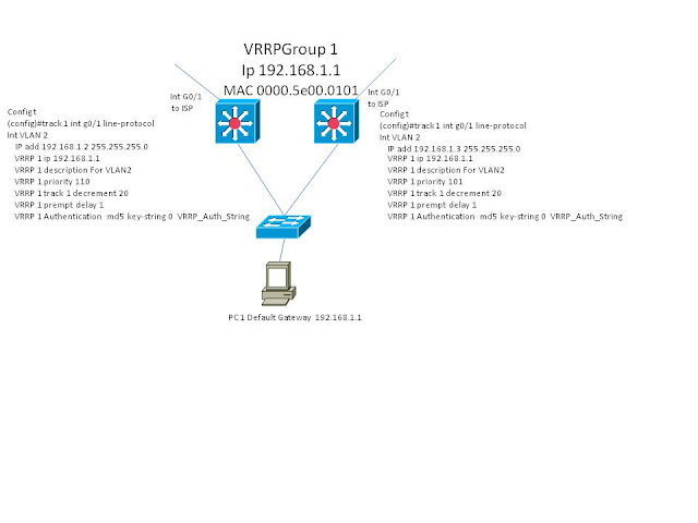
VRRP (Virtual Router Redundancy Protocol) enables a group of routers to form a single virtual router. The LAN clients can then be configured with the virtual router as their default gateway. Can use a type of load sharing with additional configuration. Is open standard (RFC 2338). It's MAC is 0000.5E00.01XX xx = the group id in HEX. It can use ether a virtual IP (like HSRP uses) OR a actual IP of the primary router (or layer 3 Sw). Has two types, Master which is forwarding traffic, and Backup which is listening for hellos from the master on 224.0.0.18. If an actual IP address is being used than that router is the Master, otherwise the router with the highest priority wins. Hellos are sent out every 1 sec by default by the Master. Backups will wait a "master down interval" before an election is held to see who has the next highest priority, and become the Master. If the original Master (or a router with a higher priority) comes up, it will immediately become master. The "master down interval" is 3x the hello + the skew time. The Skew time is (256-priority) / 256 which is the priority. If there is a tie by priority then the router with the highest IP address wins.
To configure VRRP
int vlan 2
ip add x.x.x.x s.s.s.s
VRRP 1 ip x.xx.x
xVrrp descripsion For Vlan 2
xVrrp 1 priorty 175
xVrrp 1 timer advertise 5
xVrrp 1 timers learn (on Backups to learn hello timer from Master)
xVrrp 1 preempt (delay)
xVrrp track 1 decrement 10 (the int to track in config in globle config#track 1 int f0/0 ip or line)

First hop redundancy
HSRP (Hot Standby Router Protocol), Standby hot swappable because one of the routers (or Layer 3 Sw)
is in standby mode till it is needed. Is Cisco proprietary. Has two types, Active which forward traffic, and Standby which is monitoring periodic hello for the Active.
HSRP Allows two or more layer 3 interfaces to act as the default gateway for a lan, one as active an the others in standby mode. The routers share a logical ip address and MAC the MAC is 0000.0c07.acxx, xx = the group ID
The routers send hellos to each other on 224.0.0.2 every 3sec by default and if 3 in a row are miss the router in standby takes over. If the original router comes back up, it doesn't re-assume the active roll by default, BUT can be configured to do so, and to do so after a set amount of time in order to give it time to fully boot and learn any routes ect. A router can all as lose the active roll if one of it tracked interface go down which will lower it's priority by 10 (by default),
To configure HSRP
Int Vlan 3
ip add xxx.xxx.xxx.xxB snm.snm.snm.snm
no shut
STANDBY 1 ip xxx.xxx.xxx.xxA
Standby 1 name Is_optional
Standby 1 priority 110 (default is 100)
Standby 1 track int gx/x -20 (-10 is default)
Standby 1 prempt delay (min) reload (min) (immediately is the default)
Standby 1 Authentication WORD (clear text)
Auth md5 key-string WORD (Key string) (max 64 chars)
Auth md5 key-chain Word (name of the key-chain)

Monday, March 21, 2011
More spanning-tree
Portfast - not a cisco specific feature. Configured in globle mode with "spanning-tree protfast default " or in Interface mode with "spanning-tree portfast".
-Because PortFast can be enabled on nontrunking ports connecting two switches, spanning tree loops can occur because BPDUs are still being transmitted and received on those ports. The PortFast BPDU guard feature prevents loops by moving a nontrunking port into an errdisable state when a BPDU is received on that port.
this can cause the CAM to no longer by accurite- in order to solve this the switch all flood frames with source addresses from it's CAM table and a multicast destin add to insure the frame reaches all the CAM table in the network.
*backbone fast - for indirect falures, Cisco specific feature. Configured in globle mode with "spannint-tree backbonefast". Detect indirect falures by tracking the inferior BPDU that a switch will sent out when it have a direct link failure to a root. When the swicth with the Direct failure sent it BPDU it it's BID as the root the receiving switch know there is a better root still out there.
-Because PortFast can be enabled on nontrunking ports connecting two switches, spanning tree loops can occur because BPDUs are still being transmitted and received on those ports. The PortFast BPDU guard feature prevents loops by moving a nontrunking port into an errdisable state when a BPDU is received on that port.
-By default, spanning tree sends BPDUs from all ports regardless of whether PortFast is enabled. BDPU filtering is on a per-switch basis; after you enable BPDU filtering, it applies to all PortFast-enabled ports on the switch.
-The loop guard feature checks if a root port or an alternate root port receives BPDUs. If the port is receiving BPDUs, the loop guard feature puts the port into an inconsistent state until it starts receiving BPDUs again. Loop guard isolates the failure and lets spanning tree converge to a stable topology without the failed link or bridge.
You can enable loop guard on a per-port basis with the spanning-tree guard loop command
*UP linkfast - for direct falures. Cisco specific feature Configured in globle mode with "spanning-tree uplinkfast" - puts port into farwarding state immediately, thus violating standard STP procedures. this can cause the CAM to no longer by accurite- in order to solve this the switch all flood frames with source addresses from it's CAM table and a multicast destin add to insure the frame reaches all the CAM table in the network.
*backbone fast - for indirect falures, Cisco specific feature. Configured in globle mode with "spannint-tree backbonefast". Detect indirect falures by tracking the inferior BPDU that a switch will sent out when it have a direct link failure to a root. When the swicth with the Direct failure sent it BPDU it it's BID as the root the receiving switch know there is a better root still out there.
Tuesday, March 15, 2011
Spanning tree
Loop preventsion
Loop gaurd
BPDU filter
UDLD
Spanning tree
4 Flavors
802.1 d Reg
802.1 Not Stand, PVST(only works with ISL) and PVST+(for 802.1q) Both Cisco Only!
802.1 w Rapid
802.1 s MST
Port States
* Disable
* Blocking No Packets (frames) forwarded STP still monitoring BDPUs
* Listening Processing BDPUs
* Learning Learning mac addresses and building switching table
* Forwarding Port is forwarding and receives Packets (frames) STP monitors for BDPUs
^ 802.1w
^ discarding - same as blocking
^ learning - same as learning
^ Forwarding - same as forwarding
Port Roles
*root - the port the receives the best BPDU on a switch, from the root, the port "closest" to the root (root switches do not have root ports)
*designated - the port that can sent the best BPDU on the segment. There can only be one des port on a segment
* Non-designated ports are blocking port in 802.1d STP
^ in 802.1w
^ Alternate Port - receives more useful BPDU from the same switch it is on and is in blocking. An alternate port provides an alternate path to the root bridge and therefore can replace the root port if it fails.
^ Backup port - Is in blocking, and provides redundant connectivity to the same segment and cannot guarantee an alternate connectivity to the root bridge.
Sunday, March 13, 2011
ccnp Swith
642-813 SWITCH (BCMSN) Exam Topics (Blueprint)
Exam Description
Implementing Cisco IP Switched Networks (SWITCH 642-813) is a qualifying exam for the Cisco Certified Network Professional CCNP®, and Cisco Certified Design Professional CCDP® certifications.
The SWITCH 642-813 exam will certify that the successful candidate has important knowledge and skills necessary to to plan, configure and verify the implementation of complex enterprise switching solutions using Cisco’s Campus Enterprise Architecture. The SWITCH exam also covers secure integration of VLANs, WLANs, voice and video into campus networks.
Exam TopicsThe following information provides general guidelines for the content likely to be included on the exam. However, other related topics may also appear on any specific delivery of the exam. In order to better reflect the contents of the exam and for clarity purposes the guidelines below may change at any time without notice.
Implement VLAN based solution, given a network design and a set of requirements
• Determine network resources needed for implementing a VLAN based solution on a network
• Create a VLAN based implementation plan
• Create a VLAN based verification plan
• Configure switch-to-switch connectivity for the VLAN based solution
• Configure loop prevention for the VLAN based solution
• Configure Access Ports for the VLAN based solution
• erify the VLAN based solution was implemented properly using show and debug commands
• Document results of VLAN implementation and verification
Implement a Security Extension of a Layer 2 solution, given a network design and a set of requirements
• Determine network resources needed for implementing a Security solution
• Create a implementation plan for the Security solution
• Create a verification plan for the Security solution
• Configure port security features
• Configure general switch security features
• Configure private VLANs Configure VACL and PACL
• Verify the Security based solution was implemented properly using show and debug commands
• Document results of Security implementation and verification
Implement Switch based Layer 3 services, given a network design and a set of requirements
• Determine network resources needed for implementing a Switch based Layer 3 solution
• Create an implementation plan for the Switch based Layer 3 solution
• Create a verification plan for the Switch based Layer 3 solution
• Configure routing interfaces Configure Layer 3 Security
• Verify the Switch based Layer 3 solution was implemented properly using show and debug commands
• Document results of Switch based Layer 3 implementation and verification
Prepare infrastructure to support advanced services
• Implement a Wireless Extension of a Layer 2 solution
• Implement a VoIP support solution
• Implement video support solution
Implement High Availability, given a network design and a set of requirements
• Determine network resources needed for implementing High Availability on a network
• Create a High Availability implementation plan
• Create a High Availability verification plan
• Implement first hop redundancy protocols
• Implement switch supervisor redundancy
• Verify High Availability solution was implemented properly using show and debug commands
• Document results of High Availability implementation and verification
Subscribe to:
Comments (Atom)